Modelling a Ballscrew Drive
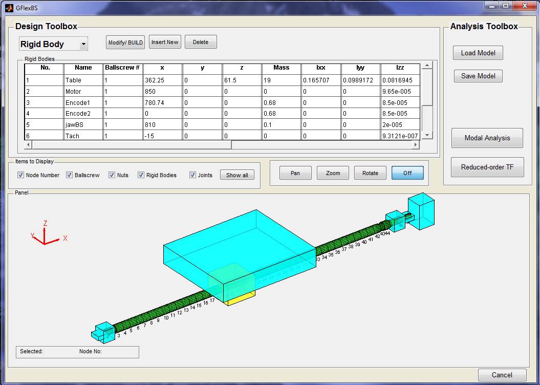
Click the ‘Feed Drive’ icon in the Axis Servo Drive module, and when the ‘Feed Drive’ icon is highlighting, select the ’Leadscrew Servo Drive’ radial button and click the ‘Flexible ballscrew Drive’ icon below. This opens the structure design interface of the flexible ballscrew drive.

By clicking the ‘Load Model’ button in the Analysis Toolbox, you can select an existing flexible ballscrew drive model under the file path ‘Virtual CNC /Ballscrew / ubcBS.mat’. After loading the structure of the example ballscrew can be shown in the interface.
In the Design Toolbox, you can select one of the four types of the structure: Ballscrew, Nut, Rigid Body and Joint. Then by clicking one item of the table and the Modify, Insert New or Delete button, you can design the structure.
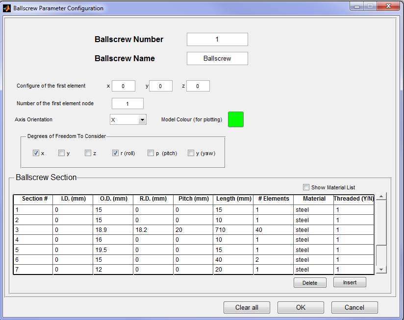
For example: after selecting Ballscrew, clicking the No.1 item in the ballscrew table, and clicking the Modify/BUILD button, the interface of Ballscrew Parameter Configuration will be open. Then you can configure the parameters of the ballscrew.

After modelling a new ballscrew structure, you should save your new model by clicking the ‘Save Model’ button in the Analysis Toolbox.